Two Core Graphics calls, swapped. The matrix behind every translateBy, rotate, and scaleBy, why the last call you write runs first, and the 54-line program that proves it on your own Mac.
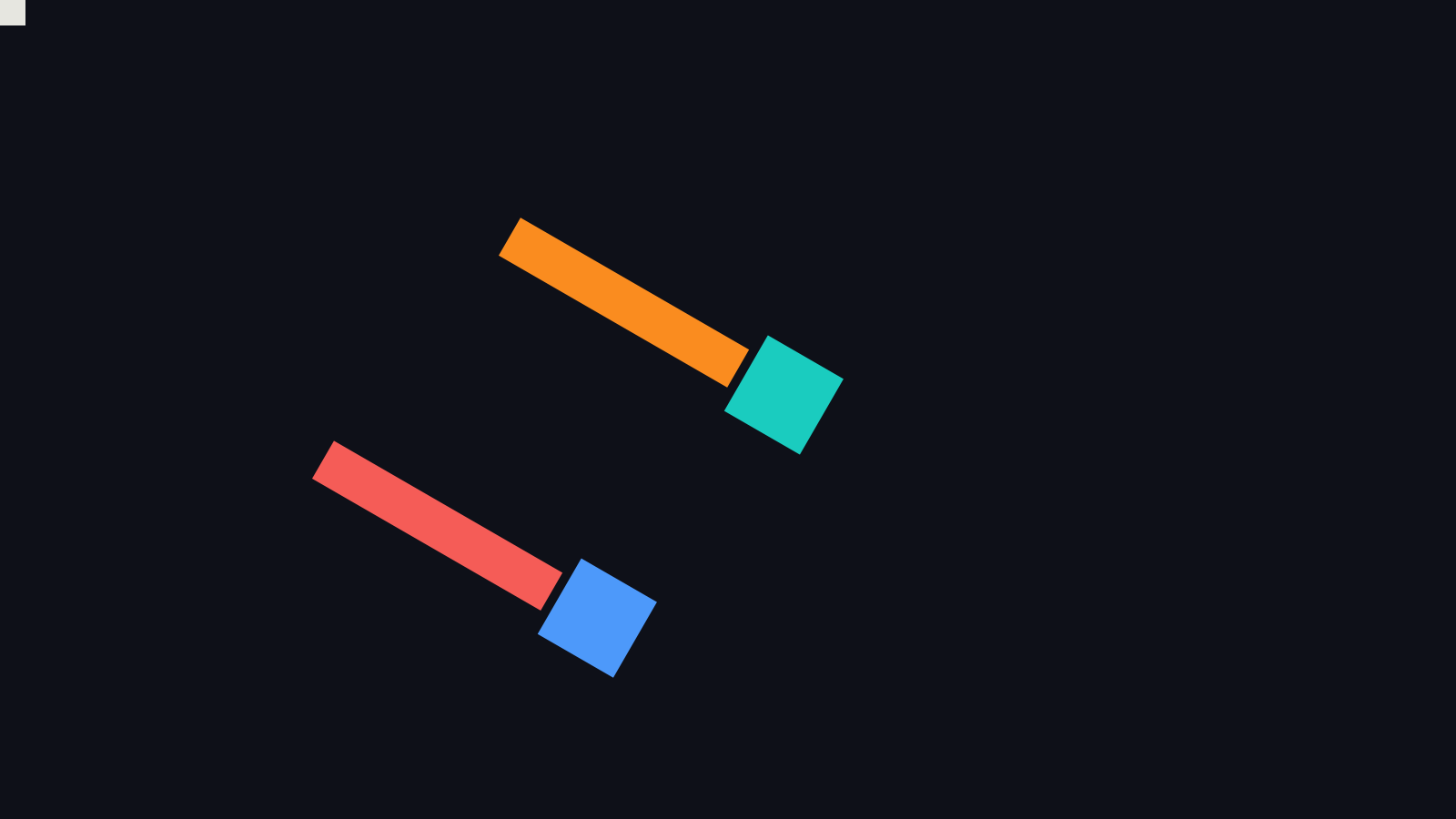
SlayerMotion render of the two arms.
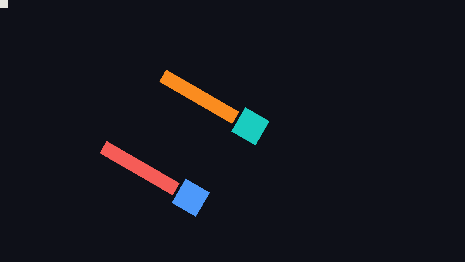
Apple render of the same scene. The pale square in the corner marks the origin. Mean difference between the two renders: 0.0007% of full scale, on anti-aliased edges only.
Welcome back.
Issue 1 gave you the map. This issue starts at the bottom of it, with a piece of state you never see and always depend on.
Both pictures above were drawn from the same two calls: move the origin by 560 across and 260 down, and rotate by 30 degrees. The orange arm and the coral arm differ in one thing only. The two lines are written in opposite orders. One order puts the arm at the top. The other puts it lower and to the left, nowhere near where you would guess.
That is the first law of the whole stack, and it comes back everywhere: in text shaping, in image filters, in layer compositing, in SwiftUI. Order matters. Here is what is underneath it.
Two Lines, Swapped
This is the whole difference. The arm and its head are drawn the same way both times: an arm of 290 by 48 starting at the origin, and a 96-point square head just past its end.
// Order A: translate, then rotate. The orange arm.
context.translateBy(x: 560, y: 260)
context.rotate(by: .pi / 6)
drawArm()

// Order B: rotate, then translate. The coral arm.
context.rotate(by: .pi / 6)
context.translateBy(x: 560, y: 260)
drawArm()
If you read the code top to bottom as a story (“move over there, then turn”), you will expect both arms to end up near (560, 260). Only the first does.
The Matrix You Never Wrote Down
Every CGContext carries a current transformation matrix, the CTM. It is six numbers, a b c d tx ty, and it maps each point you draw, in your coordinates, to a point on the page:
x' = a·x + c·y + tx
y' = b·x + d·y + ty
A fresh context has the identity: a = d = 1, everything else 0. The calls you already know each change those six numbers in a fixed way:
| Call | What it makes |
|---|---|
translateBy(x: tx, y: ty) | adds a shift: tx, ty |
rotate(by: θ) | a = cos θ, b = sin θ, c = -sin θ, d = cos θ |
scaleBy(x: sx, y: sy) | a = sx, d = sy |
concatenate(_:) | any matrix you hand it, a shear for example: c ≠ 0 |
Here is each one applied to the same square. The grey squares on the left are the starting shape. The coloured ones on the right are the result.
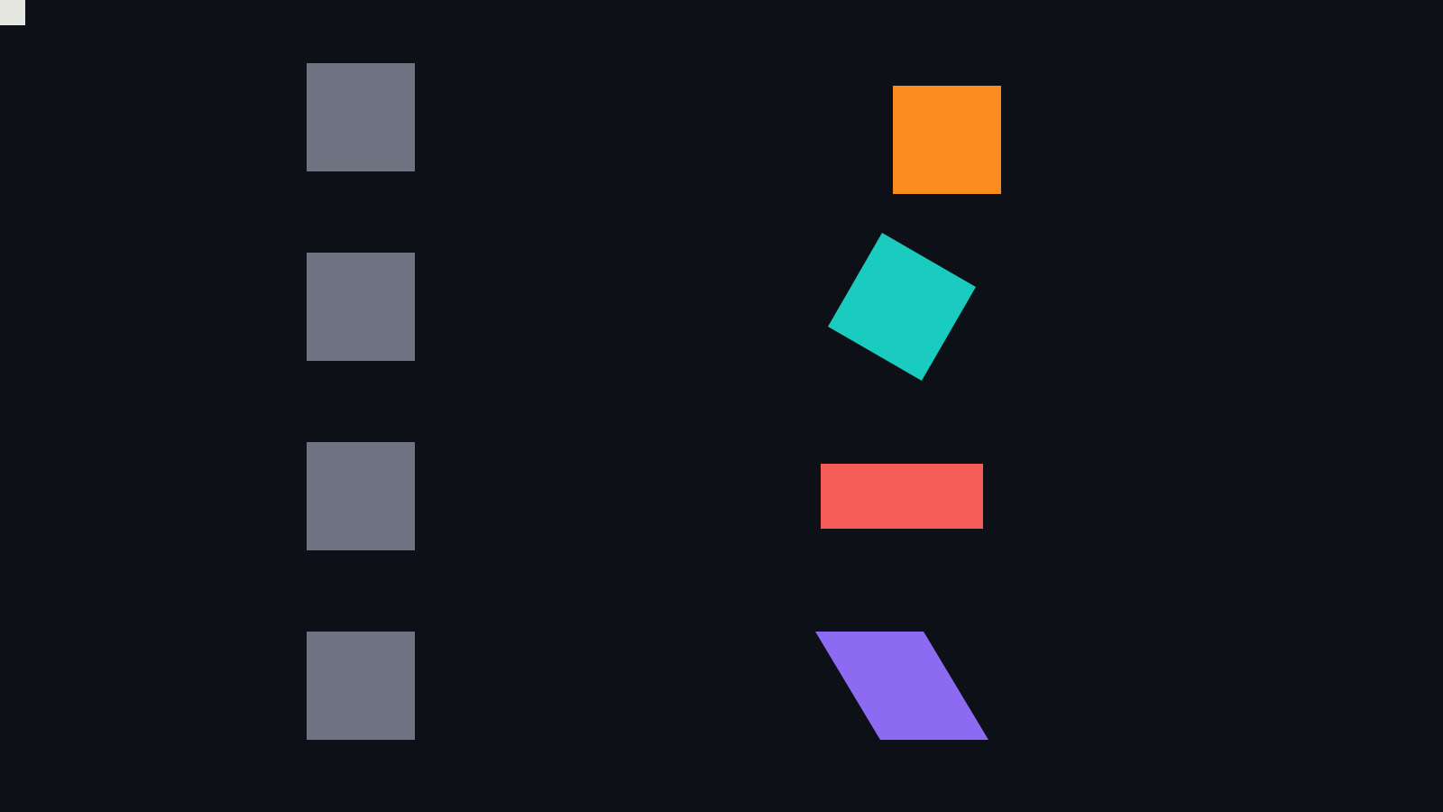
SlayerMotion render. From top: translate by (50, 25), rotate by 30 degrees, scale by (1.5, 0.6), and a shear with c = 0.6.
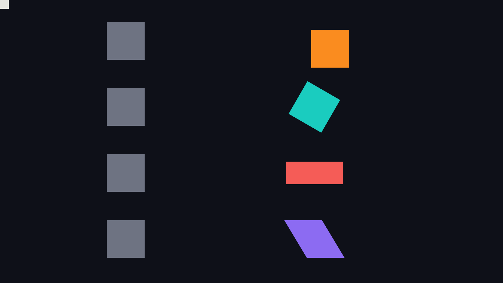
Apple render of the same scene.
The shear is written with context.concatenate(CGAffineTransform(a: 1, b: 0, c: 0.6, d: 1, tx: 0, ty: 0)). A rotation always keeps right angles, so rotating a square never produces that parallelogram. A matrix whose two columns are not at right angles can, and the shear here has c = 0.6.
Why the Last Line Runs First
Each of those calls does not replace the CTM. It composes the new operation onto the matrix that was already there, and the new operation is applied to your points first. The older state is applied afterwards.
So read order A from the bottom: your point is rotated first, about the origin you currently have, and then carried to wherever the earlier translateBy moved the origin. Read order B from the bottom: your point is moved by (560, 260) first, and then the whole thing is rotated about the original origin, which swings it around.
You do not have to take that on my say-so. Ask the context. Here is what CGContext.ctm reports on this Mac, after each order, with the page flip taken out:
translate, rotate  a=0.8660 b=0.5000 c=-0.5000 d=0.8660  tx=560.00 ty=260.00
rotate, translate  a=0.8660 b=0.5000 c=-0.5000 d=0.8660  tx=354.97 ty=505.17
Measured: printed by the program at the end of this issue, macOS 27.0.1.
Both orders have the same rotation block. They differ in the translation, and the difference has a clean explanation. In order B the shift is applied first and the rotation second, so the shift itself gets rotated:
R(30°) · (560, 260) = (560·cos 30° − 260·sin 30°,  560·sin 30° + 260·cos 30°)
                    = (354.97, 505.17)
Derived by hand, and it matches what Apple’s matrix reports to the hundredth of a point.
Take one point, (100, 0) in your drawing coordinates, through both:
| Order | Where (100, 0) lands | Derived |
|---|---|---|
| translate, rotate | (646.60, 310.00) | 0.8660·100 + 560, 0.5000·100 + 260 |
| rotate, translate | (441.58, 555.17) | 0.8660·100 + 354.97, 0.5000·100 + 505.17 |
One point, two destinations 319.6 points apart, from the same two calls.
Watching the Coordinate Frame Move
It helps to stop thinking about the point and watch the ruler. Each call moves the coordinate frame you are drawing in. The next picture draws that frame, an x axis and a y axis, after every step. The origin of this scene is at (100, 100), and the two calls are a translate by (520, 120) and a rotate by 30 degrees.
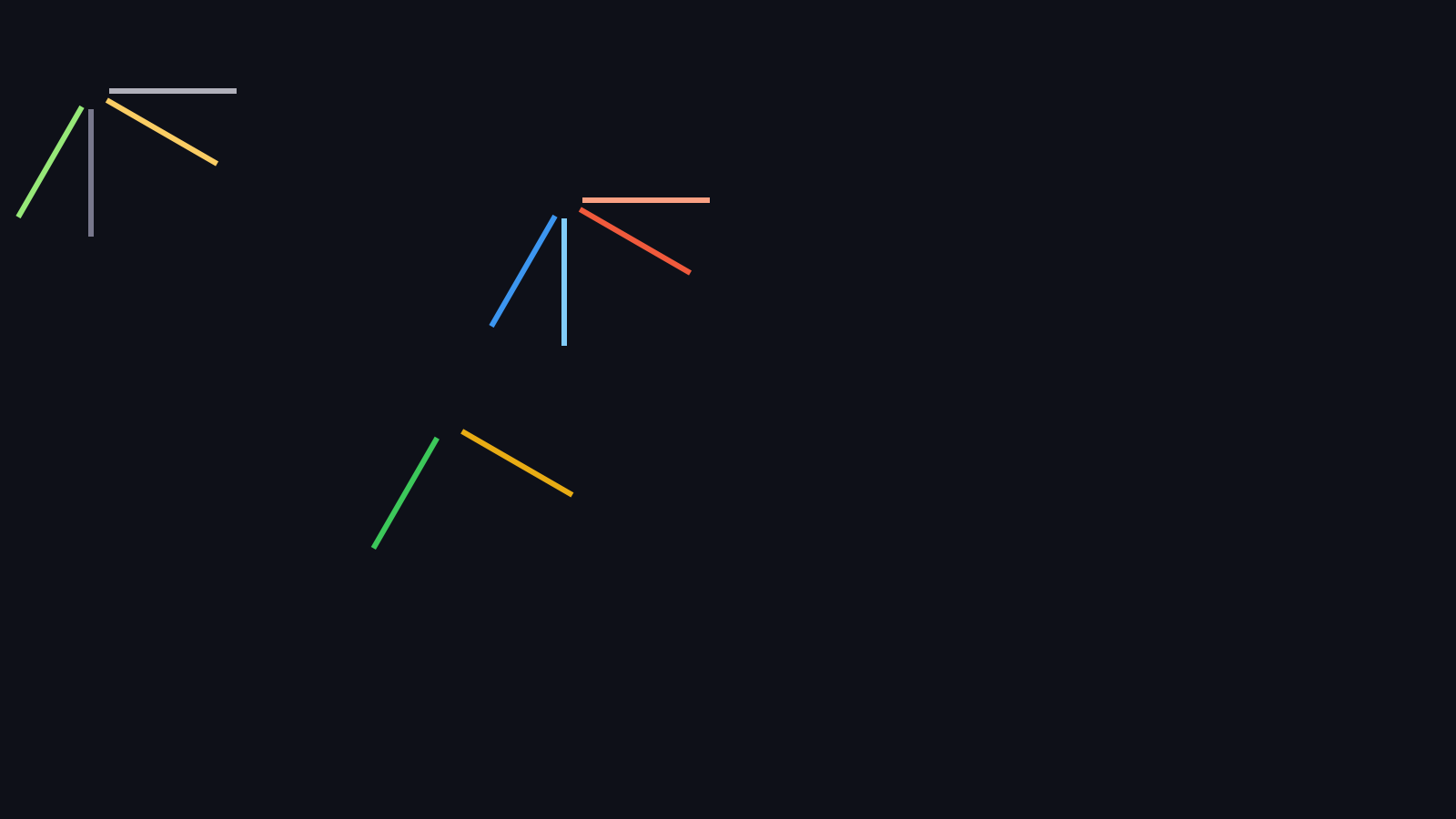
SlayerMotion render. Top left: the starting frame in grey and, at the same origin, the frame after only the rotation of order B in pale yellow and green. Middle: order A, after the translation (peach and light blue) and after the rotation (red and blue). Lower centre: order B after its translation (gold and green).
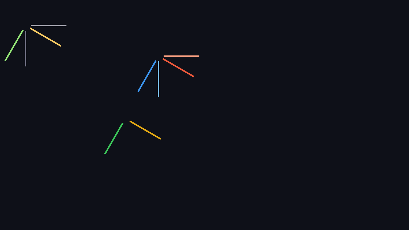
Apple render of the same scene.
Translate then rotate: the frame slides to (620, 220), then spins in place, still at (620, 220). Rotate then translate: the frame spins first, so its axes already point the new way, and the slide then happens along the rotated axis. It lands at (490.33, 463.92), derived as (100, 100) plus R(30°)·(520, 120).
That is the whole trick. A translateBy after a rotate moves you along a tilted ruler.
Watch It Move
Here is the same pair of orders as a loop. The rotation angle sweeps a full turn. On the left, translate then rotate: the arm spins in place about its own pivot. On the right, rotate then translate: the same two calls, swapped, and the arm orbits the centre.
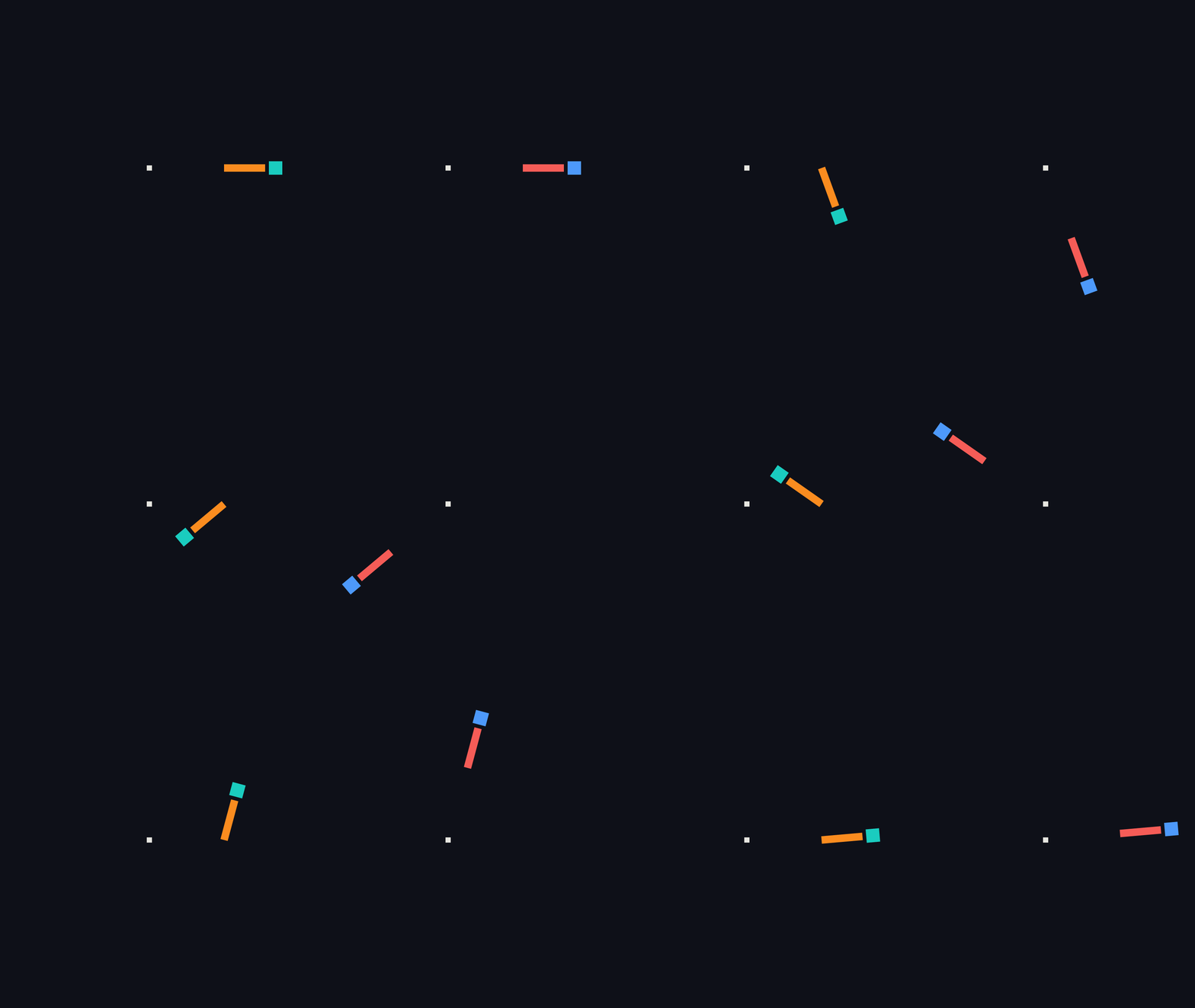
SlayerMotion render.
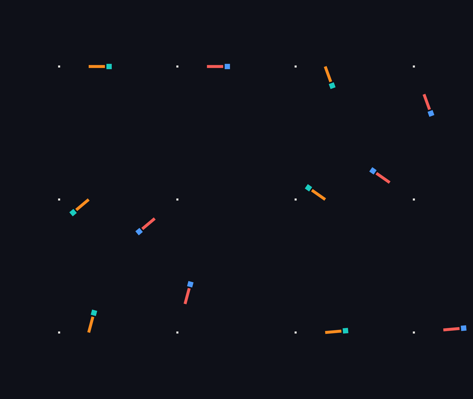
Apple render. Full-quality video: SlayerMotion, Apple.
And here is the slide. The square rotates 30 degrees and slides by an amount that grows and then shrinks. Top: slide, then rotate. The square travels along the page’s own x axis. Bottom: rotate, then slide. The slide runs along the rotated axis, so the square travels down a slope. The thin rails run parallel to each path.
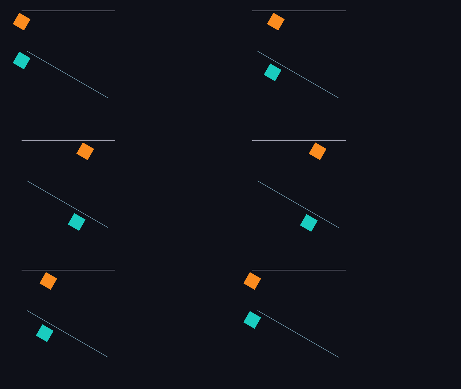
SlayerMotion render.
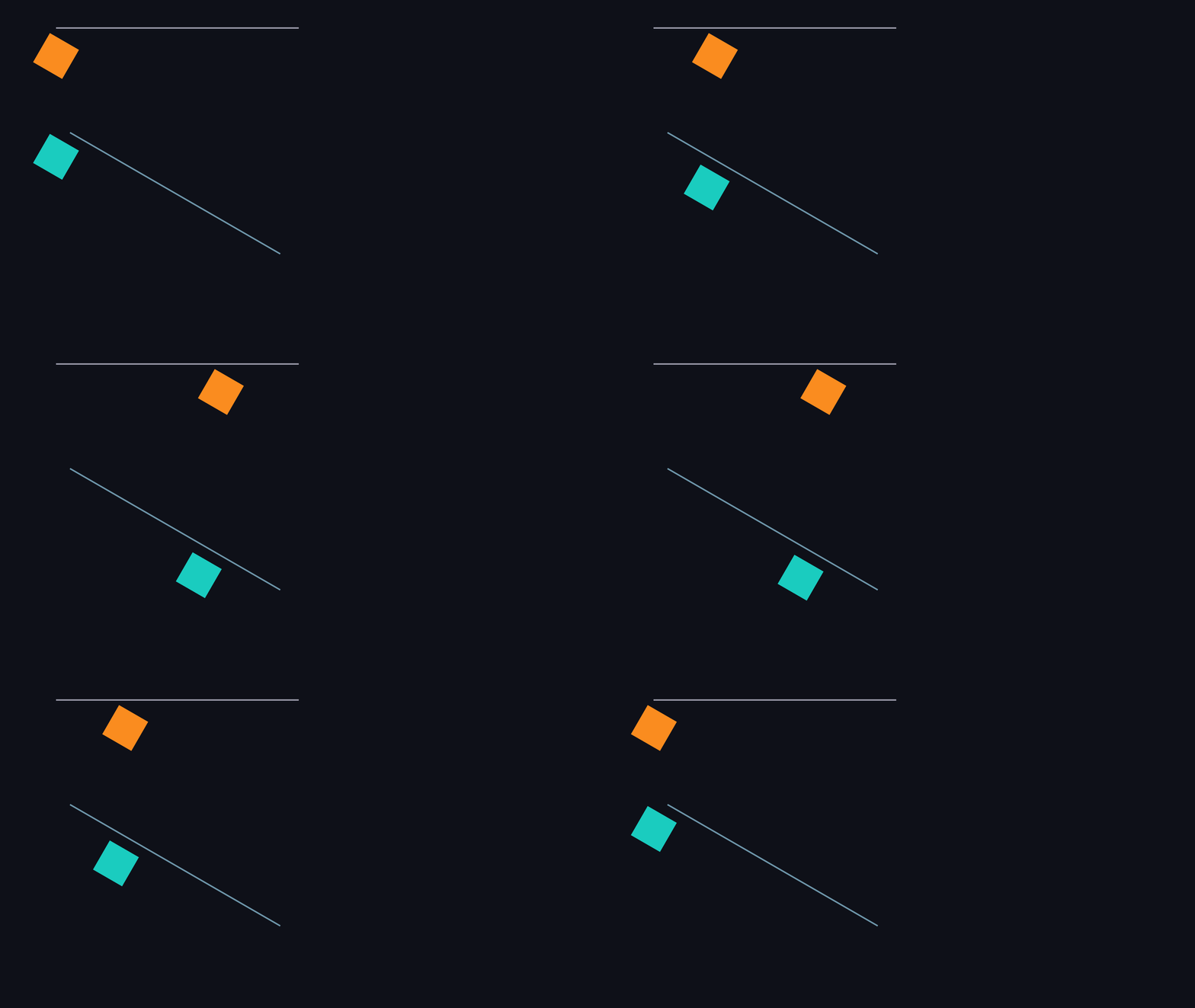
Apple render. Full-quality video: SlayerMotion, Apple.
Save and Restore Bracket the Change
The CTM is part of the graphics state, and saveGState() and restoreGState() push and pop that whole state. Anything you change between them, the CTM included, is undone at the restore. That is what lets you put a rotation around one shape without it leaking onto the next.
context.saveGState()
context.translateBy(x: 300, y: 450)

context.saveGState()
context.rotate(by: .pi / 4)
fill(coral)                      // rotated 45 degrees about (300, 450)
context.restoreGState()          // the rotation is gone

fill(teal)                       // still translated, no longer rotated
context.restoreGState()          // the translation is gone too

fill(yellow)                     // plain page coordinates again
The picture follows the same script, with two more steps: a translated and scaled square (green) and one more drawn after its restore (violet).
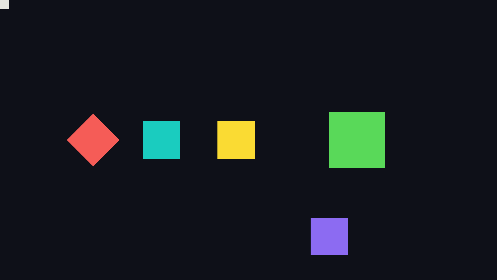
SlayerMotion render.
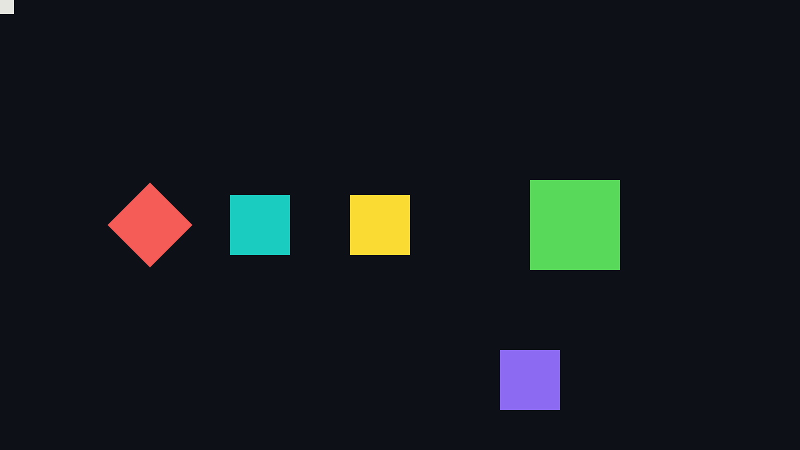
Apple render. The coral square is the only one that turns.
Each square sits exactly where its own bracket says it should, and the one outside every bracket sits where you drew it, in raw page coordinates.
Flipping the Page
A bare CGContext puts the origin at the bottom left with y pointing up. UIKit and SwiftUI draw with y pointing down, which is why you see this at the start of so much drawing code:
context.translateBy(x: 0, y: height)
context.scaleBy(x: 1, y: -1)
That is the flip, and it is nothing special. It is a translation followed by a scale, a CTM like any other. Every picture in this issue is drawn in that y-down space, which is also why a positive rotation turns clockwise on screen here and counterclockwise in a raw y-up context.
The next picture draws an asymmetric stem and flag three ways: upright, flipped about a horizontal line with translateBy(300, 760) then scaleBy(1, -1), and flipped with the whole-page flip.
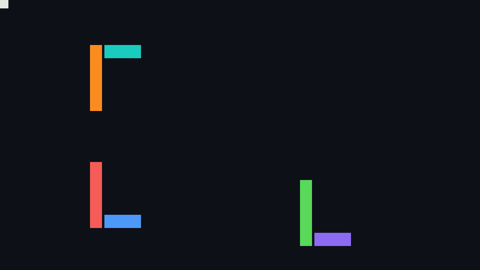
SlayerMotion render.
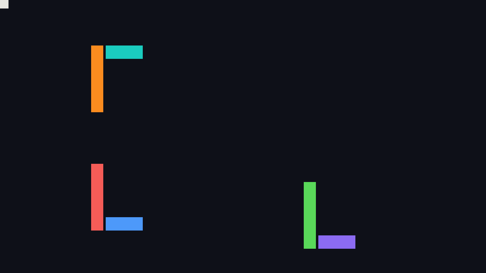
Apple render. In this scene every edge lands exactly on a pixel boundary, so there is no anti-aliasing, and the two renders are identical, byte for byte.
Same Ingredients, Different Shape
One more consequence of order, and the one that surprises people most. Take a 200 by 120 rectangle, stretch it to twice its width with scaleBy(x: 2, y: 1), and rotate it 30 degrees. Write the two calls in the two orders.
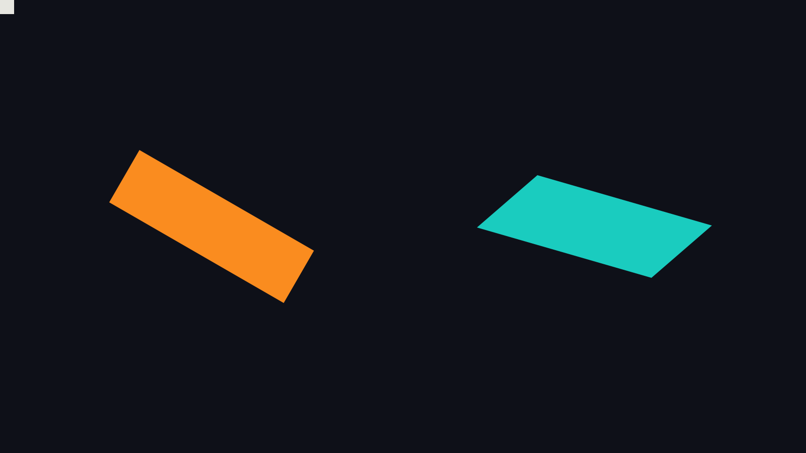
SlayerMotion render. Left: written rotate, then scaleBy. Right: written scaleBy, then rotate.
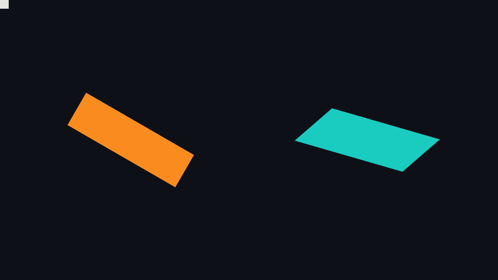
Apple render.
Written rotate then scaleBy, the stretch is applied to your points first, along the rectangle’s own width, and the rectangle then turns: it stays a rectangle. Written scaleBy then rotate, the rotation is applied first and the stretch second, along the page’s x axis: the rectangle shears into a parallelogram. The matrices say why. Both have the same determinant, 2, so both cover the same area, 48,000 square points. But their columns tell different stories:
written rotate, scaleBy:  a = 1.732  b = 1.000  c = -0.500  d = 0.866
                          columns (1.732, 1.000) and (-0.500, 0.866): dot product 0, still at a right angle

written scaleBy, rotate:  a = 1.732  b = 0.500  c = -1.000  d = 0.866
                          columns (1.732, 0.500) and (-1.000, 0.866): dot product -1.299, no longer at a right angle
Derived. In the second order the stretch acts along the page’s x axis, not along the shape’s own, and a non-uniform stretch of a turned shape is a shear.
Here it is through a full turn of the angle. Left: the rectangle just spins. Right: it swings through every kind of parallelogram.

SlayerMotion render.

Apple render. Full-quality video: SlayerMotion, Apple.
How I Checked
Every figure and every frame above was drawn twice: once by Apple’s Core Graphics, once by my own SlayerMotion renderer, from the same scene description. That would show two renderers agreeing. It would not show that either of them applies transforms in the right order. So each scene also has an answer key that neither renderer sees.
The answer key is closed-form. Each coloured shape is a solid rectangle in a colour used nowhere else in its scene. From the six matrix numbers, plain algebra predicts where its centre must land, how much area it covers, and its second moments, which are what tell a rotation from a shear. Then I measure those same three things in the rendered pixels and compare. Two rules keep the measurement honest: every bound is named, with the measured worst case printed beside it, and the same algebra with the operation order reversed has to fail. If the answer key could not tell order A from order B, it would prove nothing.
Results, measured, from the committed renders of all nine figures:
| Figure | Shapes checked | Worst centre error, SlayerMotion | Worst centre error, Apple | Reversed-order answer key misses by at least |
|---|---|---|---|---|
| Two arms | 5 | 0.0003 px | 0.0146 px | 319.6 px |
| Save and restore | 6 | 0.0000 px | 0.0000 px | 413.9 px |
| Flips | 7 | 0.0000 px | 0.0000 px | 1,520.0 px |
| Stretch and rotate | 3 | 0.0000 px | 0.0209 px | 206.7 px |
| Coordinate frames | 10 | 0.0010 px | 0.0079 px | 73.2 px |
| Elementary transforms | 9 | 0.0000 px | 0.0083 px | 456.0 px |
| Rotation sweep, 72 frames | 432 | 0.0020 px | 0.0083 px | 65.4 px |
| Slide, 72 frames | 288 | 0.0015 px | 0.0326 px | 109.8 px |
| Shear sweep, 72 frames | 144 | 0.0000 px | 0.0446 px | 131.7 px |
Across all 904 shape-checks (every shape in every figure and every animation frame), both renderers land within 0.05 pixels of the algebra on the centre, and agree with it on area and shape within named bounds. The worst case belongs to Apple’s render of the shear sweep, at 0.0446 pixels. The answer key for the wrong order is far from every render: on each shape that the wrong order would move by more than 5 pixels, which is most of them, the nearest the render comes to the wrong prediction is 65.4 pixels.
The two renders are not byte-identical where anti-aliasing exists, and they should not be. They differ on edge pixels only: mean difference between 0.0001% and 0.0020% of full scale across every figure and every animation frame. Where every edge falls exactly on a pixel boundary, as in the flip scene and in the four quarter-turn frames of the rotation and shear sweeps, the two renders must be identical, and they are.
The checks caught me first. My first verification run had two failures, and both were mine. I had set an area bound without measuring it, and described it in a comment as measured. And I had required the two renders to differ in a scene with no anti-aliasing at all, where identical output is the correct answer. The later runs found three flaws in the instrument itself: marker colours that were not exact 8-bit values, which inflated the errors in the first scene roughly tenfold; two markers touching at an edge, which blurred both; and the faint edge pixels of a neighbouring shape leaking into the tally of a thin bar. I fixed the instrument. Area and shape errors also had to change units: a rasterizer’s coverage error lives on boundary pixels, so a long thin bar is almost all boundary, and I now measure those errors per unit of perimeter. Then I set each bound at about three times its measured worst case. A bound you wrote before you measured is a guess. A bound you loosened after a failure is a decision, and you owe your reader the reason.
Run It Yourself
You do not need my renderer for any of this. This is the whole Apple half, a standalone Core Graphics program. It draws the first figure, prints the two matrices above, and writes order-matters.png:
import CoreGraphics
import Foundation
import ImageIO
import UniformTypeIdentifiers

// Colours in the same device RGB space as the bitmap, so nothing is converted.
let deviceRGB = CGColorSpaceCreateDeviceRGB()
func rgb(_ r: Int, _ g: Int, _ b: Int) -> CGColor {
    CGColor(colorSpace: deviceRGB, components: [CGFloat(r) / 255, CGFloat(g) / 255, CGFloat(b) / 255, 1])!
}

// A 1600 x 900 bitmap whose y axis points down, like UIKit and SwiftUI.
let context = CGContext(
    data: nil, width: 1600, height: 900, bitsPerComponent: 8, bytesPerRow: 0,
    space: deviceRGB, bitmapInfo: CGImageAlphaInfo.premultipliedLast.rawValue
)!
context.translateBy(x: 0, y: 900)
context.scaleBy(x: 1, y: -1)
let flip = context.ctm
context.setFillColor(rgb(14, 16, 24))
context.fill(CGRect(x: 0, y: 0, width: 1600, height: 900))

func report(_ label: String) {
    let m = context.ctm.concatenating(flip.inverted())   // the matrix, without the flip
    print(String(format: "%@  a=%.4f b=%.4f c=%.4f d=%.4f  tx=%.2f ty=%.2f", label, m.a, m.b, m.c, m.d, m.tx, m.ty))
}

func drawArm(arm: CGColor, head: CGColor) {
    context.setFillColor(arm)
    context.fill(CGRect(x: 0, y: -24, width: 290, height: 48))
    context.setFillColor(head)
    context.fill(CGRect(x: 300, y: -48, width: 96, height: 96))
}

// Order A: translate, then rotate.
context.saveGState()
context.translateBy(x: 560, y: 260)
context.rotate(by: .pi / 6)
report("translate, rotate")
drawArm(arm: rgb(250, 140, 31), head: rgb(26, 204, 191))
context.restoreGState()

// Order B: rotate, then translate. Same two calls, swapped.
context.saveGState()
context.rotate(by: .pi / 6)
context.translateBy(x: 560, y: 260)
report("rotate, translate")
drawArm(arm: rgb(245, 92, 87), head: rgb(77, 153, 250))
context.restoreGState()

let url = URL(fileURLWithPath: "order-matters.png")
let destination = CGImageDestinationCreateWithURL(url as CFURL, UTType.png.identifier as CFString, 1, nil)!
CGImageDestinationAddImage(destination, context.makeImage()!, nil)
CGImageDestinationFinalize(destination)
Save it as ctm.swift and run xcrun swiftc ctm.swift -o ctm && ./ctm on a Mac. On the machine that produced this issue, its output matches the Apple figure at the top of this page in 0 of 1,440,000 pixels, apart from the corner origin mark that this program leaves out. Measured, macOS 27.0.1.
One detail is worth a sentence because it silently changes every pixel. Build your colours in the same colour space as your bitmap. A colour made with CGColor(red:green:blue:alpha:) is sRGB. Drawn into a device RGB bitmap it is converted, and every pixel shifts by several values, so your output differs from mine everywhere for a reason that has nothing to do with transforms.
What This Issue Does Not Prove
This issue covers filled rectangles under a CTM built from translateBy, rotate, scaleBy, and concatenate, with saveGState and restoreGState, in an 8-bit premultiplied device RGB bitmap at 1x, in software, on macOS 27.0.1. It does not cover how the CTM interacts with stroking, where a non-uniform scale also stretches the line width; with clipping; with text, which has its own matrix; with patterns and shadows; with other colour spaces; or with 2x and 3x scale factors and GPU-backed contexts. Those are not claims I am making. They are the next things to measure.
Where We Go Next
Next is the rest of Core Graphics state: paths, and the clip that decides which pixels may change at all. Same method: one claim, drawn twice, measured against an answer key neither renderer can see.
See you in Issue 3.
The books behind this newsletter. Core Graphics, Core Text, Core Image, Core Animation and SwiftUI, every chapter drawn twice and measured against an answer key. See the books.